System Solver: User's Guide
The System Solver was developed to support you and your students'
understanding of systems of linear equations. The System Solver offers
users the unique opportunity to perform operations on a system and
immediately observe the graphic, tabular, and symbolic results of the
procedure at each step. Using the System Solver, you can:
- Select symbolic forms for different equations
- See the graphic results of operations on individual equations and systems
- See the graphic consequences of combining equations
- View the relationship between tabular results and graphic representations
Table of Contents
Getting to Know the System Entry Interface
Entering a System
The Main System Solver Interface
Working with the Graph Window
Working with the Coordinate Table
Performing an Operation on Both Sides of the System
Combining Equations
Deleting and Starting Over
The About Button
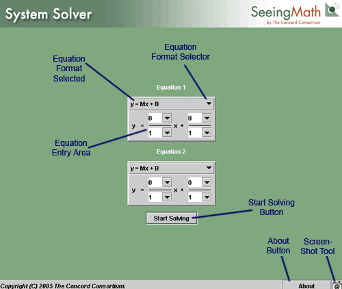
When you start the System Solver, the first screen is the system
entry interface shown below. The interface contains two equation entry
dialog boxes. This is the place where you select your equation form and
enter the equations for the system you wish to solve. Each of these
areas is explained in detail in this guide.
System Entry Interface
As you go through this material, it's convenient to open the System
Solver in a separate window so that you can work with the tool while
following the instructions. Click System Solver to launch the interactive. When the System Solver launches, you will see the default values shown above.
Note If you click the
Start Solving button immediately, before entering values, you will get
a message indicating that the system that you have submitted is a
dependent system. If at any time you find you have entered a system
that gives you an error message, you can click on the Start Over button
to return to the system entry interface (see Deleting and Starting Over
below).
In order to show you how the System Solver works, you'll be guided
through a typical system solution that demonstrates the functionality
of each part of the System Solver. Start with the following system.

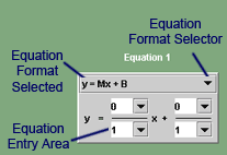
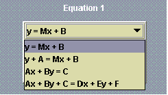
- To select an appropriate equation format, click the
Equation Format Selector and view the four equation formats to chose
from. These should accommodate most of the system formats that you will
encounter.
Note Although
the illustrations and examples are shown in the dialog labeled Equation
1, the operation is identical for Equation 2.
Equation Entry Dialog Box |
Equation Format Selections |
- For our example, select the second format for Equation
1. Once you have selected the format, it appears at the top of the
dialog.
- Enter the values for Equation 1 into the Equation
Entry Area. You must enter a numerator as well as a denominator for
each value.
- Select a format in the dialog labeled Equation 2, and enter values into the Entry fields.
- You should now have a set of dialogs like the illustration below. Click the Start Solving button to accept your entries and advance to the main System Solver interface.
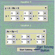
Equation Entry Dialog Boxes
Now that you have entered a system and clicked on the Start Solving button, the System Solver presents the main interface. Take a moment to note each part of the interface.
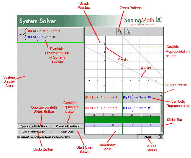
Main System Solver Interface
The main Graph Window contains a Cartesian plane showing a gray
line on the x-axis and the y-axis for each equation in your system.
There are also tools that allow you to modify the display. At the top
of the screen are the Zoom buttons.

Zoom Buttons
- Click the magnifying icon with the plus sign to "zoom in."
- Click the magnifying glass icon with the minus sign to "zoom out" and see a greater area.
As
shown below, when you zoom out, you see a larger area of the plane. A
blue and a red dot correspond to the colors of the equations below the
Graph Window. The red dot is on the line represented by Equation 1. The
blue dot is on the line that represents Equation 2. In this example,
they share a common x-coordinate.
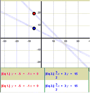
A Shared x-Coordinate in the Graph Window
In the Coordinate Table (see below), you can see the shared x-coordinate is −6.
Note
Scroll across the Graph Window by moving your cursor over the window
until the cursor changes its shape to a hand. Then, click and hold
while moving the Graph Window to reveal additional area.
Below the Graph Window is the Tabular Area of the interface.This is
where your two current system equations are displayed in the Symbolic
Representation area. There is also a Coordinate Table with a row of
numbers and a Slider Bar for displaying more values. The row of numbers
represents the coordinates of the red and blue indicators in the Graph
Window.
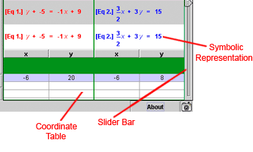
Tabular Area
- Click and hold the wedge-shaped Slide Control on the Slider
Bar and move it up and down. You will see that three things happen.
- In
the Graph Window, if you have maintained the earlier position, a series
of additional red and blue coordinate indicators appear moving along
the length of the lines, including an intersection point.
- In
the Coordinate Table, you see coordinate sets that each correspond to
one pair of red and blue indicators on the Graph Window.
- The
lower set of Symbolic Representations of each equation change in a
manner corresponding with the highlighted line on the Coordinate Table.
- Move your mouse and click on any of the coordinate indicators in the Graph Window.
- The corresponding line of coordinates in the Coordinate Table highlight.
- The Symbolic Representations change to match.
- Click on a line of coordinates in the Coordinate Table.
- Corresponding coordinate indicators highlight.
- Note
that one set of coordinates in the table is in bold text. That line
represents the coordinates where the two lines intersect. The Symbolic
Representations change to match.
The traditional way to find the intersection of a system is through
algebraic operations. The System Solver allows you to perform an
operation on both sides of an equation within a system, using dialog
boxes.
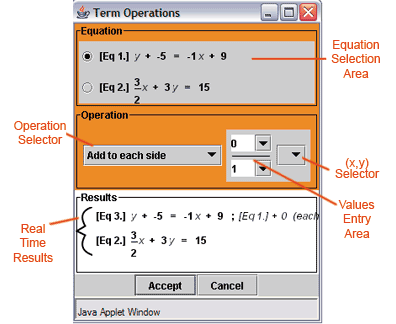
- Click on the Operate on Both Sides button to bring up the Term Operations Dialog Box.
Operation Selection Buttons
|
Term Operations Dialog Box |
- In the Equation Selection Area, select which equation in the
system you want to perform the operation on by clicking the
corresponding radio button to the left.
- As you can see in the illustration above, Equation 1 has been selected.
- In
the Operation section, the Operation Selector allows you to choose
which type of operation to perform on the selected equation.

Operation Selections
- In this example, select "Add to each side" as the operation to perform on Equation 1.
- In the Values Entry Area, enter the whole number 5.
- Since you must use fractions, enter the number 5 in the numerator.
Make sure the denominator is 1. You can also use the drop-down arrows
next to the Values Entry Area to select your entries. Doing so permits
the Real Time Results section at the bottom of the dialog to preview
your results. This allows you to experiment with several different
possibilities before making a final operation decision.
- To the right is the (x, y) Selector. If you were performing the operation on one of the variables, you would have selected it there.
- After entering the values and choosing "Add to each side," click on the Accept button at the bottom of the dialog.
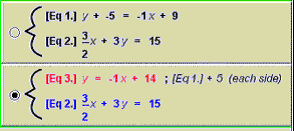
- The
resulting system retains the colors of the original equations, with
Equation 1 and Equation 3 remaining red. Notice that the equations
represented in the Tabular Area also change to reflect the currently
selected system representation. Clicking the radio button next to the
original set returns the color (and operational) focus to them and
changes the Tabular Area representation as well.
- Returning the focus to the second representation of the system shows that our operation has now successfully defined y in terms of x by isolating y on one side of Equation 3. A note to the right of the equation reminds us how we achieved that result.
Next, you will perform a function operation on the selected system, substituting Equation 3 into Equation 2.
- With the system of Equation 3 and Equation 2 selected, click on the Combine Equations button.
Operation Selection Buttons
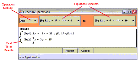
This brings up the Function Operations Dialog.
Function Operations Dialog
- The Equation Selectors allow you to choose which equation will
operate on the other. In this example, we want to reverse the default
order shown and have Equation 3 operate on Equation 2. To do so, click
on the Equation Selectors and choose the appropriate equations from the
resulting menu.
Note that as you do so, the results in the Real Time Results
section change to show how your operation will be reflected in a new
equation, Equation 4.
- The default operation is Add. In this case, we want you to
Substitute Equation 3 into Equation 2 rather than add. Click on the
Operation Selector to show the types of operations you can apply.
Scroll down and click on Substitute.

Function Operations Selections
Note that when you choose Substitute, the new Equation 4, in the
Real Time Results area, changes to reflect the result of the operation.
- Click the Accept button to accept the operation. You should now see results in your System Display Area.
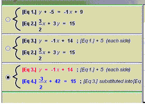
Result of Second Operation
- If you now continue by subtracting 42 from both sides of Equation
4, dividing each side of the resulting Equation 5 by -2/3, and then
substituting Equation 6 into Equation 3, you will have solved the
system and have a System Display Area that looks like the following
illustration.
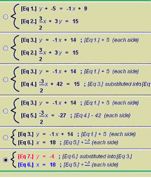
System Display Area Showing Solved System
You have solved the system and found that the coordinates of (y = −4) and (x = 18) are the intersection point of the system.
The last two buttons of interest in the Symbolic Representation Area are the Undo button and the Start Over button.

Undo Button and Start Over Button
- Clicking on the Undo button takes you back one step in your solving process.
- Clicking on the Start Over button ends your current system session and returns you to the System Entry Interface where you can enter a new system.
Note
You can't delete your initial system using the Undo button. If you wish
to delete that system, use the Start Over button instead.

The About Button
Clicking on the About button brings up the About
the System Solver pop-up. You can view the version number of the System
Solver you are running, as well as find Credits and Acknowledgements.
The version number can be very helpful if you need to ask for Technical
Support or run into unexpected operational issues.
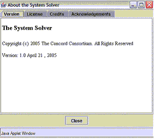
The About the System Solver Pop-up


